Hardware and setup
The imaging quality of Widepix 1×5 MPX3 imaging detector operated in the time-delayed-integration (TDI) mode has been tested on steel welds. The setup parameters were:
– X-ray tube at 120 kVp and 8 mA
– DIQ/IQI to detector distance was 16 mm
– Source-to-detector distance 800 mm
– UR-3e robot for detector movement
– Robot scan speed 0.7 mm/s (TDI speed)
The detector used in this evaluation was Widepix 1×5 MPX3 with parameters:
– Row of five Medipix3 chips
– 1280×256 pixels, pixel size 55 μm
– CdTe sensor 1 mm thick
– Discrimination thresholds were 10 keV for CSM and 60 keV for signal
The device was tested on BAM-5 and BAM-25 steel weld samples with IQI and DIQI attached on them. The detector-to-sample distance was set as short as possible to minimise the geometrical unsharpness in order to evaluate only the detector properties and not the influence of the X-ray tube spot size.


Widepix 1×5 MPX3 CdTe photon counting detector
The detector was operated in a charge-summing-mode (CSM) that corrects on the spread of signal between neighbouring pixels. The CSM mode significantly improves the detector spectral response and therefore also allows setting a high discrimination threshold to minimise contribution of the scattered radiation. The reduction of scattered radiation increases the achieved contrast and therefore also detail detectability.
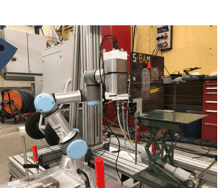
The detector was operated in the time-delayed-integration mode (TDI). It was moved along the sample by a robotic arm. The speed of movement and the detector readout were synchronised. The detector then produced a scan along the axis of movement. The TDI is directly supported by the hardware.

Imaging test setup. The detector was attached to UR-3e robot that was moving along the sample at a constant speed. The X-ray tube position was fixed. The sample was placed as close to the detector as possible to minimise the geometrical unsharpness and thus evaluating only the detector properties.
Results
The measured images were corrected using the signal-to-thickness calibration where the number of photons is converted to an equivalent thickness of a calibration material. In this case, the calibration material was steel. The spatial resolution was measured using DIQI. The narrowest wire pair resolved was the D13 (50 μm wide wires with gap of 50 μm) .

Signal of the wire pair D13 behind the BAM-5 sample.
The signal-to-noise ratio measured (SNRm) achieved was of 148 in case of 8.3 mm thick BAM-5 sample. SNRm of 190 was measured for the BAM-25 which is of 6 mm thick steel. The SNRm was capped by the X-ray tube power. The detector has 24-bit counter depth therefore allowing SNRm as high as 4000.
The resulting SNRn (normalised on the detector resolution) was of 336 at 6 mm thick steel and 262 in the case of 8.3 mm thick steel.
Detector contrast was evaluated using the 10FEEN IQI. All wires including the wire 16 (0.1 mm thick) were resolved behind the 8.3 mm thick steel sample wall.

10FEEN IQI wires behind BAM-5 sample.


BAM-5 and BAM-25 steel weld inspection test samples. The BAM-25 had the DIQI with range extended to the wire D17. Both samples had 10FEEN IQI attached as well.

Selected area with micro bubbles in the BAM-5 sample weld. The image was high-pass filtered.


Resulting BAM-5 (top) and BAM-25 (bottom) sample X-ray scans. The images were processes by subtracting 50% of signal smoothed by Gaussian filter with sigma of 8.5 pixels.